Surface velocity flow meter (DVFM)
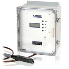
DEPTH VELOCITY FLOW MONITOR
The DVFM was developed as a flow meter for open channels such as sewers. It calculates the cross-sectional area of the flow from the water level signal sent from a sensor installed in the measurement channel, and the average flow velocity from the flow velocity signal, and then multiplies these values to convert them into flow rate.The water level, flow velocity and flow rate are displayed on the LCD and output as analog signals and integrated pulse signals (optical MOSFET).In addition, limit alarms can be set by programming and output as relay contact signals.
Main function
1. Calculate flow rate from water level and flow velocity values
2. Display of water level, flow velocity and flow rate values
3. Display of flow rate total
4. Limit alarm status display
5. Analog output of water level, flow velocity and flow rate
6. Flow rate totalizing pulse output
7. Limit alarm output
8. Watchdog Output9. Programming (Setup)
10. Water level calibration and output test using software
specification
Measurement target
General sewage, rainwater, industrial wastewater, agricultural water, river water, etc.
Main unit
| Main material | Made of resin |
| size | W345×H421×D202 (cable lock and latch not included) |
| display | LCD (20 full-width rows x 4 columns) |
| Ambient temperature | 0 to 50°C (however, avoid direct sunlight) |
| Ambient humidity | 25 to 95% RH (no condensation) |
| attachment | Rear mounting type (recommended for installation inside the panel) |
sensor
| Main material | Made of urethane resin |
| size | W34.5×H32×L203 |
| Water level measurement part | SUS316 diaphragm type |
| range | 3.5m, 10m |
| pressure resistance | 3.5m range: 14m, 10m range: 42m |
| Water level accuracy | 3.5m range: ±2% (relative to actual water level) ±3mm10m range: ±2% (relative to actual water level) ±10mm |
| Flow velocity measurement part | Ultrasound Doppler |
| range | 0 to ±5 m/s, bidirectional measurement possible |
| Measurement Mode | Forward, reverse, unidirectional, bidirectional |
| Flow velocity accuracy | ±2% FS |
| Dedicated cable | Standard 30m |
| Ambient temperature | 0 to 50°C |
| attachment | Fixed to the bottom of the waterway using dedicated mounting brackets (standard) |
Flow Measurement Accuracy
±5 to 10% RD (Accuracy can be improved by correcting flow rate)
Analog Output
| score | Standard 3 points (select from water level, flow velocity, and flow rate) |
| kinds | DC4~20mA (maximum load resistance 1000Ω) |
Flow Pulse Output
Optical MOSFET (withstand voltage 200V, load current 150mA)
Contact Output
| Contact Capacity | Relay contact (DC24V 1A, AC110V 0.5A) |
| kinds | Limit alarm (2 points): Select from water level, flow velocity, and flow rateWatchdog pulse: Output when malfunction occurs due to some cause |
program
| Display content | Water level, flow velocity, flow rate value or limit alarm status |
| set up | Parameters and various outputs |
| Parameters | Circular pipe, rectangular culvert, canal with haunch*Special canal shapes require separate ROM creation. |
power supply
AC100V 50/60Hz, power consumption 20W
Body mass
Approximately 7kg
Measurement principle
The water level is detected as water pressure by a diaphragm pressure transducer at the bottom of the sensor. A pressure-receiving element whose resistance changes with pressure changes is embedded inside the transducer, and the change in resistance is amplified as a change in voltage and output to the converter. The sensor cable has a built-in air tube, and the transducer is compensated for atmospheric pressure.Flow velocity is obtained by detecting the Doppler effect of ultrasonic waves emitted from the front of the sensor into the water. Ultrasonic waves emitted into the water are reflected by air bubbles and impurities in the water. These objects move with the flow according to the flow velocity distribution in the waterway, and the average flow velocity can be obtained by analyzing the received signal accompanied by the Doppler effect. Flow rate (Q) can be obtained by multiplying the cross-sectional area of the flow (A), calculated geometrically from the water level, by the average flow velocity value (V). (Q=V・A) Measurement values can be output as analog signals, and an integrated flow rate pulse can also be output.
Installing the sensor
The sensor is generally fixed to the bottom of the measurement channel using a dedicated mounting bracket.
Related Equipment
JIS compliant products (planned:
JIS B 7557 Drainage flowmeters - for trade or certification ), portable electromagnetic flow meters, portable surface velocity/PBF flow meters, rectifiers (baffles, blocks, etc.), flow monitoring systems (packet communications, cloud, regional IP networks, telemetry, etc.), IoT compatible